
Hardware
Phase correct active cross over rev0
An active cross over circuit that reduces distortion, cost, critical components, and the effects of drift in component values.

Crossover designs.
Passive filtering.
Traditional high fidelity speaker systems typically included either a 2 or 3 way passive crossover circuit to split the amplifier output signal based on the frequencies the drivers are designed for. Passive cross over circuits can be expensive and introduces unwanted artefacts.
Active filtering.
Active cross overs involve filtering the signals at line level, and using a separate power amplifier for each of the drivers. Active cross overs are more stable, produce less distortion and are cheaper. However, they do require separate power amplifiers for each driver units. In the past, this held major cost implications, but as the cost of silicon keeps falling year after year, the argument against active cross over becomes less and less relevant with each passing year.
Traditional design drawbacks.
Total system frequency response.
A traditional crossover design filters the highs, lows and mids separately. This makes the tolerance and drift of the components critical, as matching these components affects total system frequency response.Critical component matching.
The traditional crossover's reliance on critically matched parts has a huge cost implication. As a passive crossover acts on the amplifiers output signal, the components have to be high current, high voltage, high accuracy, and very stable. In short, although a bad but cheap crossover can be build, a good passive cross over is usually quite expensive.The Damping Factor.
The damping factor of modern amplifiers may be impressive, but passive crossovers can destroy it at certain frequencies. Around the crossover frequency, the series components in passive crossovers makes amplifier damping factor practically irrelevant as the series impedance increases towards the crossover frequency. Because of poor driver tracking, the result is increased distortion and ringing at these critical frequencies.
A new approach to active crossover design.
The active crossover circuit below does not require high voltage or high current components as it operates at line level. Importantly the circuit achieves a perfect flat total system frequency response, even with components that are neither high tolerance or highly stable. This is achieved by only having one filter circuit to filter one of the outputs, the other is being generated as the difference between the input and the filtered output signal.
This design provides good damping factor, by virtue of being active, providing a direct connection between power amplifier and driver. This ensures optimal driver tracking, reducing distortion.
The circuit is to be supplied a dual rail power supply and can be powered with anything from +5V -5V to +15V -15V.
A two driver configuration

A three driver configuration

RC Spreadsheet
Download the R C calculation spreadsheet here .2 way Printed Circuit Boards
Part list
| Designator | Package | Quantity | Designation |
|---|---|---|---|
| R2,R3,R8,R9 | Res_TH_0,25W | 4 | 2k2 |
| R4,R7 | Res_TH_0,25W | 2 | 13k7 |
| P1 | st_3_5.08 | 1 | CONN_01X03 |
| U1,U2 | DIP-8__300 | 2 | NE5532 |
| D1 | led3mm | 1 | Green |
| P3,P4,P5 | st_2_5.08 | 3 | CONN_01X02 |
| C1,C3 | C_Rect_L7.2mm_W3.5mm_P5.00mm_FKS2_FKP2_MKS2_MKP2 | 2 | 10nf |
| C7 | C_Rect_L7.2mm_W5.5mm_P5.00mm_FKS2_FKP2_MKS2_MKP2 | 1 | 1uF |
| R11 | Res_TH_0,25W | 1 | 4k7 |
| C5 | npcap_thp_5mm | 1 | 100nF |
| C6 | C_Radial_D6.3_L11.2_P2.5 | 1 | 220uF35V |
| R12 | Res_TH_0,25W | 1 | 22k |
Here are pictures of the different layers of the double sided sided through hole plated board.

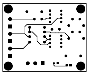

Download
Here are PDFs for all of the layers.2 way Silkscreen
2 way Top layer
2 way Bottom layer
3 way Printed Circuit Boards
Part list
| Designator | Package | Quantity | Designation |
|---|---|---|---|
| R6,R1 | Res_TH_0,25W | 2 | 5k36 |
| R2,R3,R5,R8,R9,R10 | Res_TH_0,25W | 6 | 2k2 |
| R4,R7 | Res_TH_0,25W | 2 | 13k7 |
| P1 | st_3_5.08 | 1 | CONN_01X03 |
| U1,U2 | DIP-8__300 | 2 | NE5532 |
| D1 | led3mm | 1 | Green |
| P3,P4,P5,P2 | st_2_5.08 | 4 | CONN_01X02 |
| C1,C3 | C_Rect_L7.2mm_W3.5mm_P5.00mm_FKS2_FKP2_MKS2_MKP2 | 2 | 10nf |
| C7 | C_Rect_L7.2mm_W5.5mm_P5.00mm_FKS2_FKP2_MKS2_MKP2 | 1 | 1uF |
| R11 | Res_TH_0,25W | 1 | 4k7 |
| C5 | npcap_thp_5mm | 1 | 100nF |
| C6 | C_Radial_D6.3_L11.2_P2.5 | 1 | 220uF 35V |
| R12 | Res_TH_0,25W | 1 | 22k |
| C2,C4 | C_Rect_L7.2mm_W4.5mm_P5.00mm_FKS2_FKP2_MKS2_MKP2 | 2 | 220nF |
Here are pictures of the different layers of the double sided sided through hole plated board.


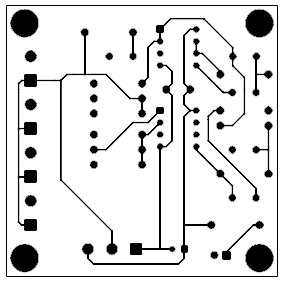
Download
Here are PDFs for all of the layers.3 way Silkscreen
3 way Top layer
3 way Bottom layer
Shop
2 way kits
| A pair of 2 way PCBs $20 (free shipping) |
A pair of Unassembled 2 way Kits $30 (free shipping) |
A pair of Assembled 2 way boards $40 (free shipping) |
|---|---|---|
NOTE COVID-19 POSTAL DELAY 3 to 4 MONTHS! |
NOTE COVID-19 POSTAL DELAY 3 to 4 MONTHS! |
NOTE COVID-19 POSTAL DELAY 3 to 4 MONTHS! |
3 way kits
| A pair of 3 way PCBs $20 (free shipping) |
A pair of Unassembled 3 way Kits $31 (free shipping) |
A pair of Assembled 3 way boards $41 (free shipping) |
|---|---|---|
NOTE COVID-19 POSTAL DELAY 3 to 4 MONTHS! |
NOTE COVID-19 POSTAL DELAY 3 to 4 MONTHS! |
NOTE COVID-19 POSTAL DELAY 3 to 4 MONTHS! |
| Home |  |